In the previous post, it was noted that bit 30 needs to be set in the i.MX6UL pad config if you want to read the state of a GPIO output. Digging into this a bit more, we find the following text in the Documentation/devicetree/bindings/pinctrl/fsl,imx-pinctrl.txt file:
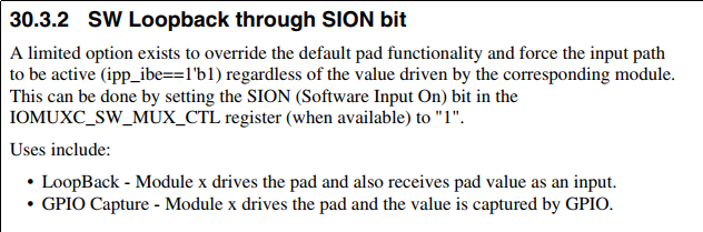
SION(1 << 30): Software Input On Field.
Force the selected mux mode input path no matter of MUX_MODE functionality. By default the input path is determined by functionality of the selected mux mode (regular).
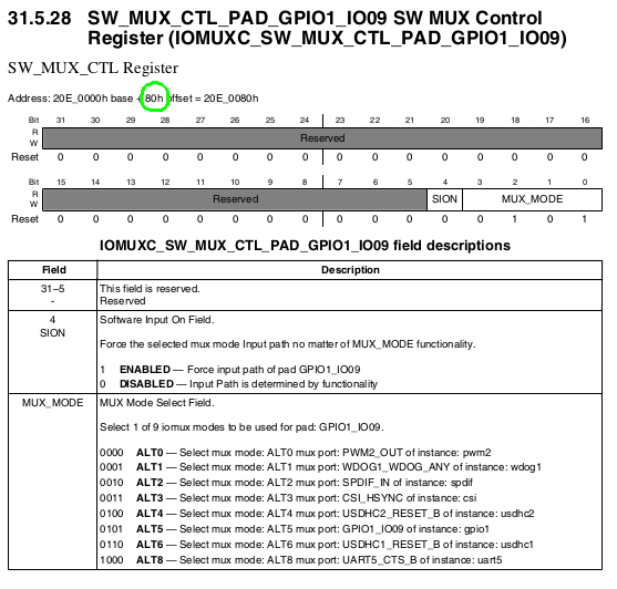
In the i.MX6UL developers manual, we also find the following:
When we look at the SW_MUX_CTL register, we notice the SION bit is located at the bit 4 position.
So the question is: How does bit 30 in the device tree file get mapped to bit 4 in the SW_MUX_CTL register? In the Linux kernel source we find the following:
drivers/pinctrl/freescale/pinctrl-imx.c:
/* The bits in CONFIG cell defined in binding doc*/
#define IMX_NO_PAD_CTL 0x80000000 /* no pin config need */
#define IMX_PAD_SION 0x40000000 /* set SION */

...

 /* SION bit is in mux register */
 config = be32_to_cpu(*list++);
 if (config & IMX_PAD_SION)
 pin->mux_mode |= IOMUXC_CONFIG_SION;
 pin->config = config & ~IMX_PAD_SION;
drivers/pinctrl/freescale/pinctrl-imx.h
#define IOMUXC_CONFIG_SION (0x1 << 4)
From this code, we can see that bit 30 is a virtual bit that gets translated into bit 4 in the mux mode register.
Hope this helps in understanding how to configure the i.MX6UL gpio. Once you understand the details; the process is very simple.